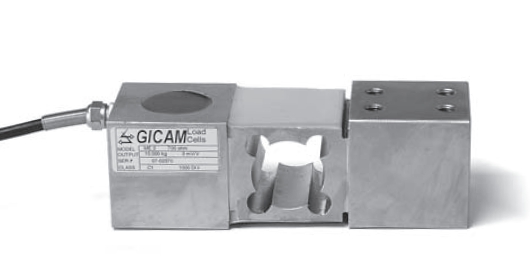
Off-center load cell for weighing systems, automatic dosage machines, medical, food, textile, and automation in general
Off-center load cell
Upon request with certification ATEX or IECEx.
Omologated C3 OIML.
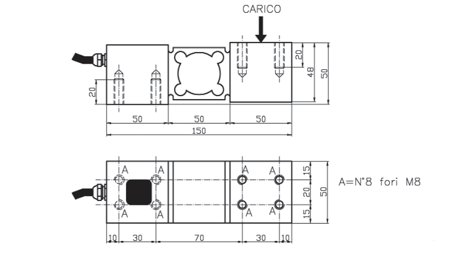
![]() Click to enlarge image
Click to enlarge image


| Material | Steel |
| Nominal load | 50, 100, 150, 200, 360 kg |
| Limit load | 150 % F.S. |
| Breaking load | 300 % F.S. |
| Supply voltage | Vcc 15 Max |
| Output | 2 mV/V |
| Output tollerance | 0,1 % F.S. |
| Zero tollerance | 1 % F.S. |
| Linearity | 0,03 % F.S. |
| Hysteresis | 0,03 % F.S. |
| Reapeatability | 0,03 % F.S. |
| Input resistance | 380-386 ohm |
| Output resistance | 350-353 ohm |
| Insulation resistance | >= 2000 Mohm |
| Creep (30 Minutes) | 0,03 % F.S. |
| Thermal compensation | -10 / +40°C (14 / +104°F) |
| Operating temperature | -20 / +70°C (-4° / +158°F) |
| Temperature deviation zero | 0,003 % F.S. / °C |
| Temperature deviation full scale | 0,002 % F.S. / °C |
| Protection class | IP 65 |
| Standard cable length | 5 m – 6 x 0,30 (shield not connected to the load cell body) |
| Type | SHIELDED CABLE 6C R6 PVC 6X0,30 |
| Length | 5 m (body lead cell not connected shield) |
| Red | + IN |
| Black | - IN |
| Yellow | + REF |
| Blue | - REF |
| Green | + OUT |
| White | - OUT |
General precautions to be followed in the installation and assembly of load cells: